Industrial Manufacturing Plant
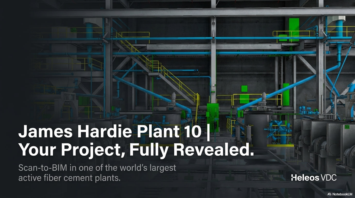
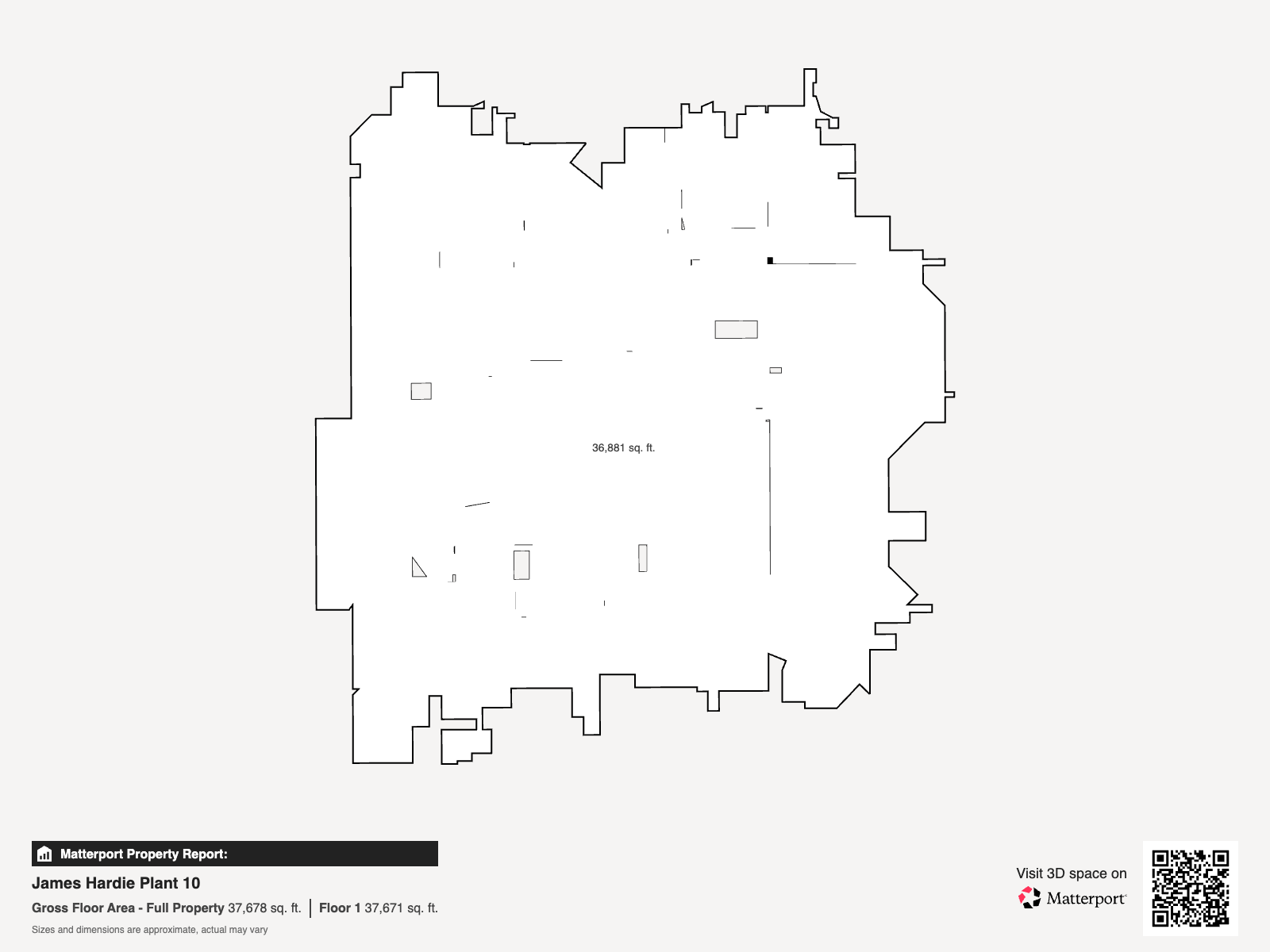
James Hardie Plant 10
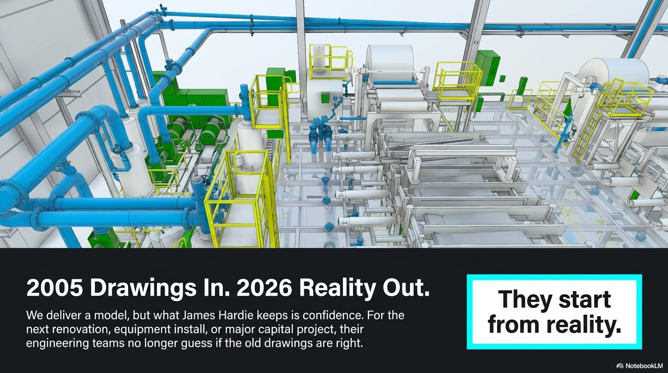
How Heleos VDC laser-scanned and modeled James Hardie's live fiber cement Plant 10 in Pulaski, VA — turning 2005 drawings and two decades of undocumented field changes into an accurate, coordinated as-built Revit model the team can build against.
Project Facts
- Location: Pulaski, VA
- Building type: Fiber cement manufacturing plant (industrial)
- Size: ~40,000 sq ft production & warehouse
- Primary service: 3D Laser Scanning & Scan-to-BIM
- Services used: 3D Laser Scanning, Scan-to-BIM, BIM Coordination
- Model level: LOD 400 federated Revit model
- Tools: Leica RTC360 / BLK360, Leica Cyclone REGISTER 360 PLUS, Autodesk Revit, Matterport, Navisworks
- Deliverable: Registered point cloud, federated architectural/structural/MEPF Revit model, 2D documentation & Matterport
- Heleos Complexity Rating: 7.5
Project Overview
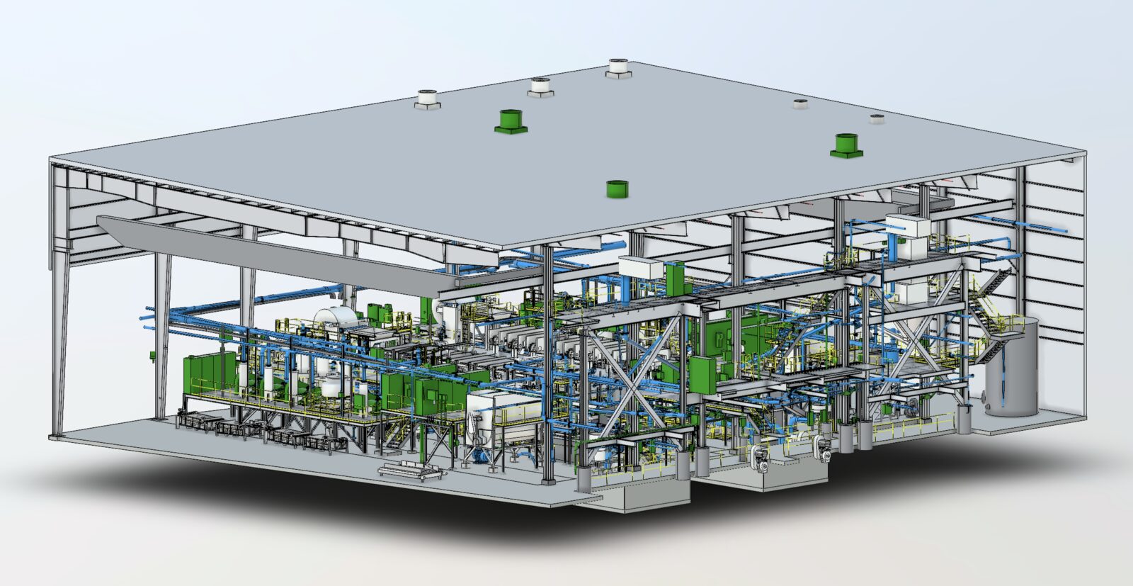
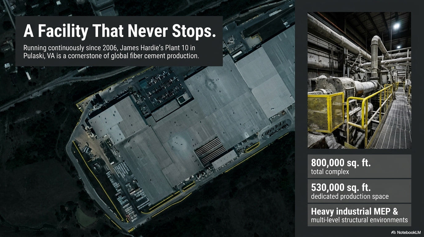
James Hardie's Plant 10 in Pulaski, Virginia is one of the largest fiber cement manufacturing plants in the world — roughly 40,000 square feet of production and warehouse space that has run continuously since 2006.
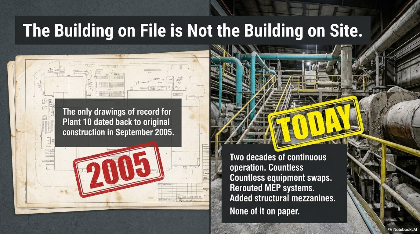
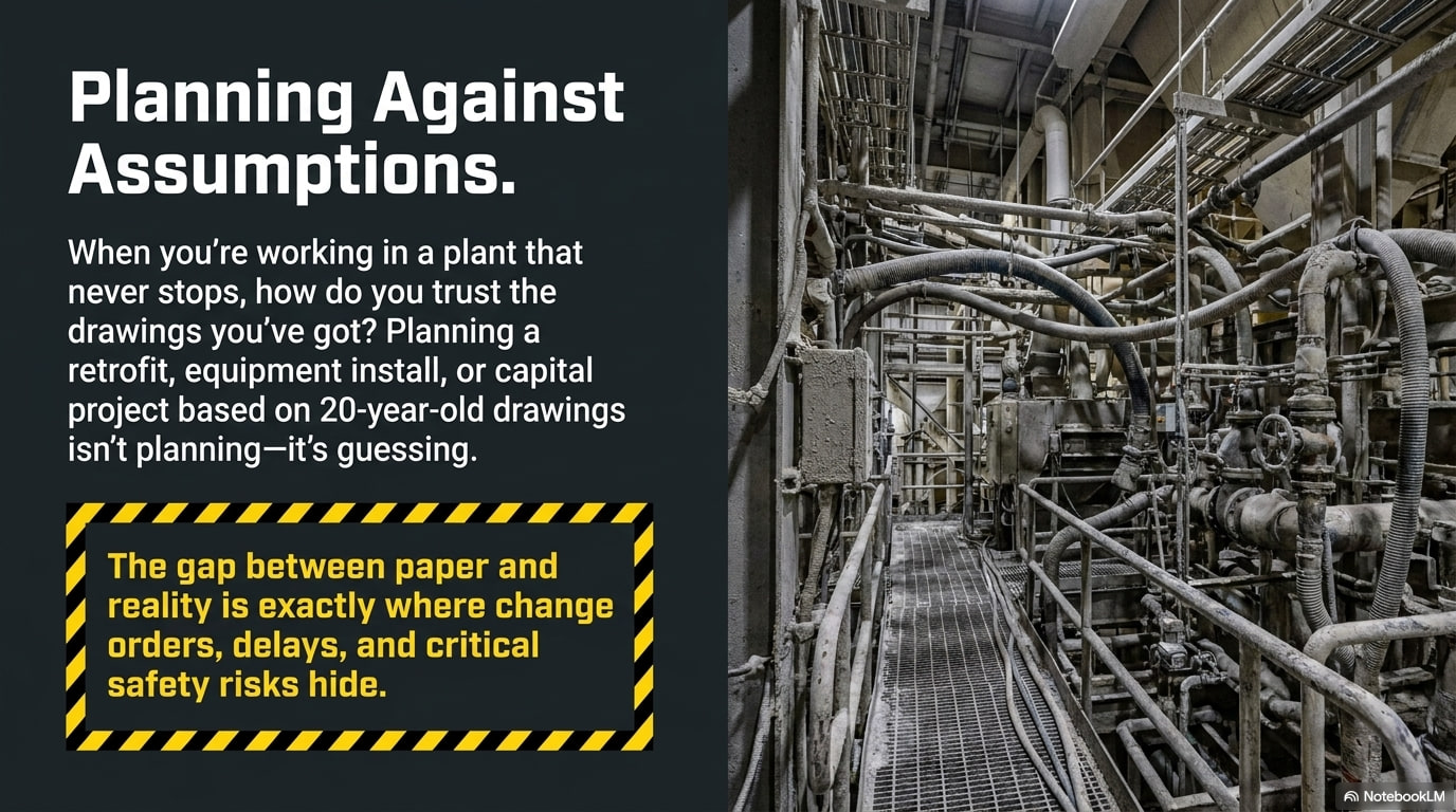
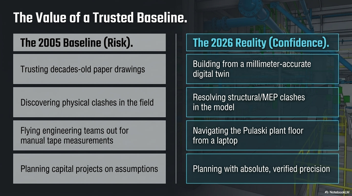
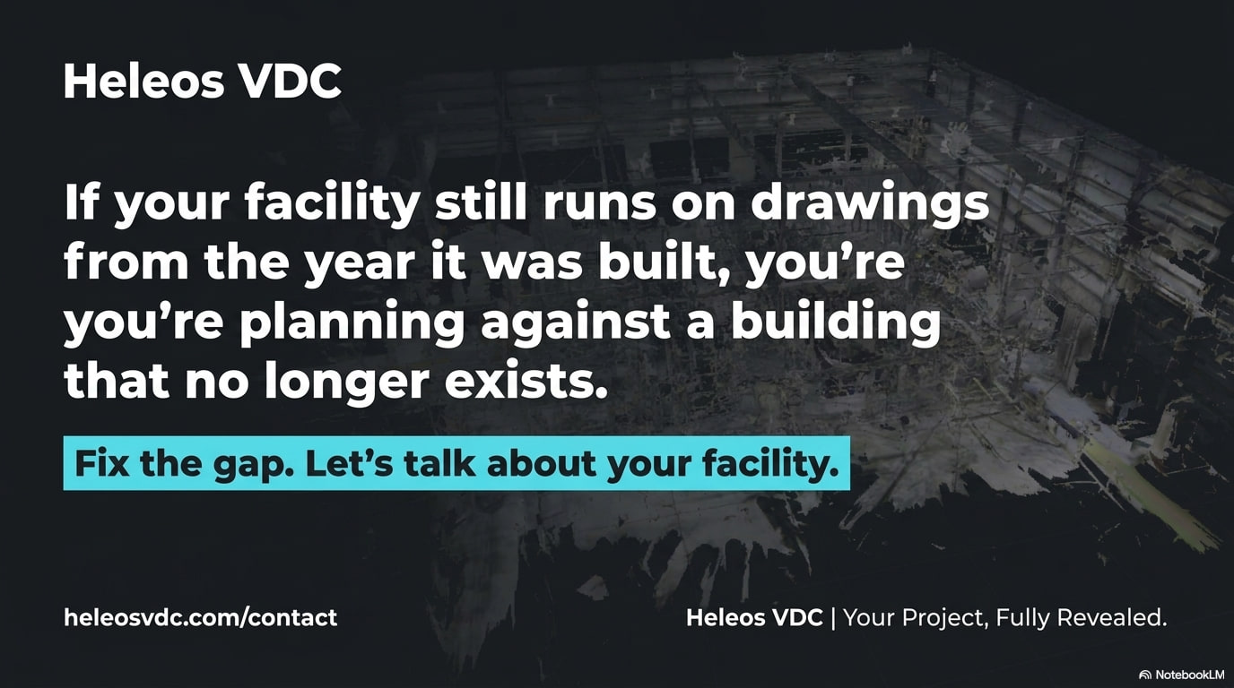
The building James Hardie operates today is not the building on file. The drawings of record date to 2005. In the two decades since, the plant absorbed the changes every working facility does: equipment swapped out, mechanical and electrical systems rerouted, structural steel reinforced, mezzanines and platforms added — none of it on paper. When the team needed to plan work inside the live process area, the existing documents could not be trusted to match the field.
James Hardie brought that problem to Heleos VDC. The assignment was direct: capture the existing conditions exactly as they stand, and deliver a coordinated model the team can actually build against.
Floor Plans
The Challenge
Documenting a live manufacturing plant is harder than documenting an empty shell. The only drawings available dated to the original 2005 construction, so nothing on paper could be assumed to match the field after twenty years of continuous operation.
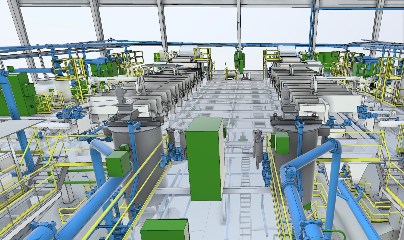
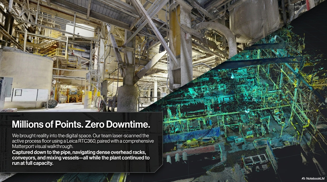
A working plant that never stops. Capture had to happen around active production — dense process equipment, conveyors, mixing vessels, and crews on the floor — with no clean, empty rooms to scan.
Twenty years of undocumented change. The only drawings available dated to original construction in 2005. Every field modification since then was invisible to the design intent, so nothing on paper could be assumed correct.
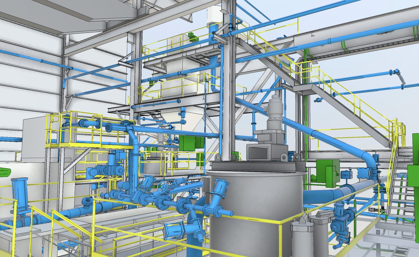
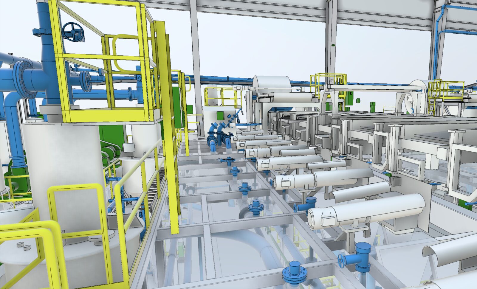
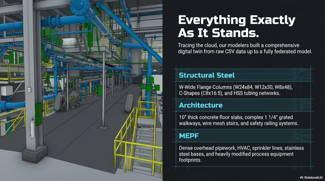
Congested, multi-level MEP. Overhead pipe racks, ductwork, electrical, sprinkler, and standpipe runs stack tightly across mezzanines and structural steel. Accurate routing and clearances demanded reality capture, not estimation.
Our Workflow
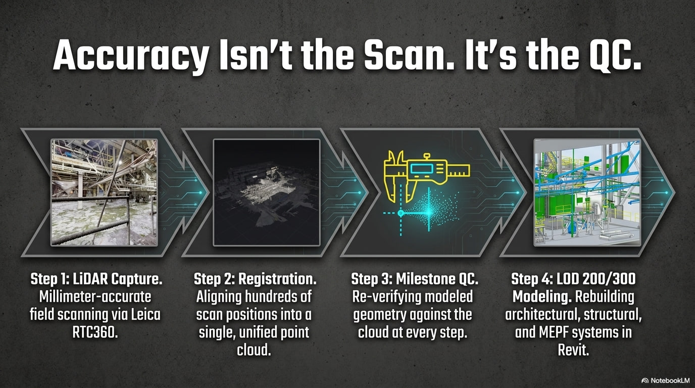
- Scan the live process area with Leica RTC360 / BLK360 LiDAR and Matterport, working around active production to capture existing conditions in place.
- Register and QA-check the scans in Leica Cyclone REGISTER 360 PLUS, then publish a complete point cloud (RCS / RCP) as the single source of truth.
- Author a federated architectural, structural, and MEPF Revit model at LOD 400, built to match the point cloud rather than the 2005 drawings.
- Produce annotated 2D floor plans, reflected ceiling plans, and CAD files drawn directly from the as-captured model.
- Quality-check portions of the model back against the point cloud at every milestone, then hand off the model, point cloud, drawings, and a navigable Matterport digital twin.
What We Delivered
- Full LiDAR + Matterport capture — on-site reality capture of the process area with a Leica RTC360 / BLK360 scanner and Matterport, registered and QA-checked in Leica Cyclone REGISTER 360 PLUS.
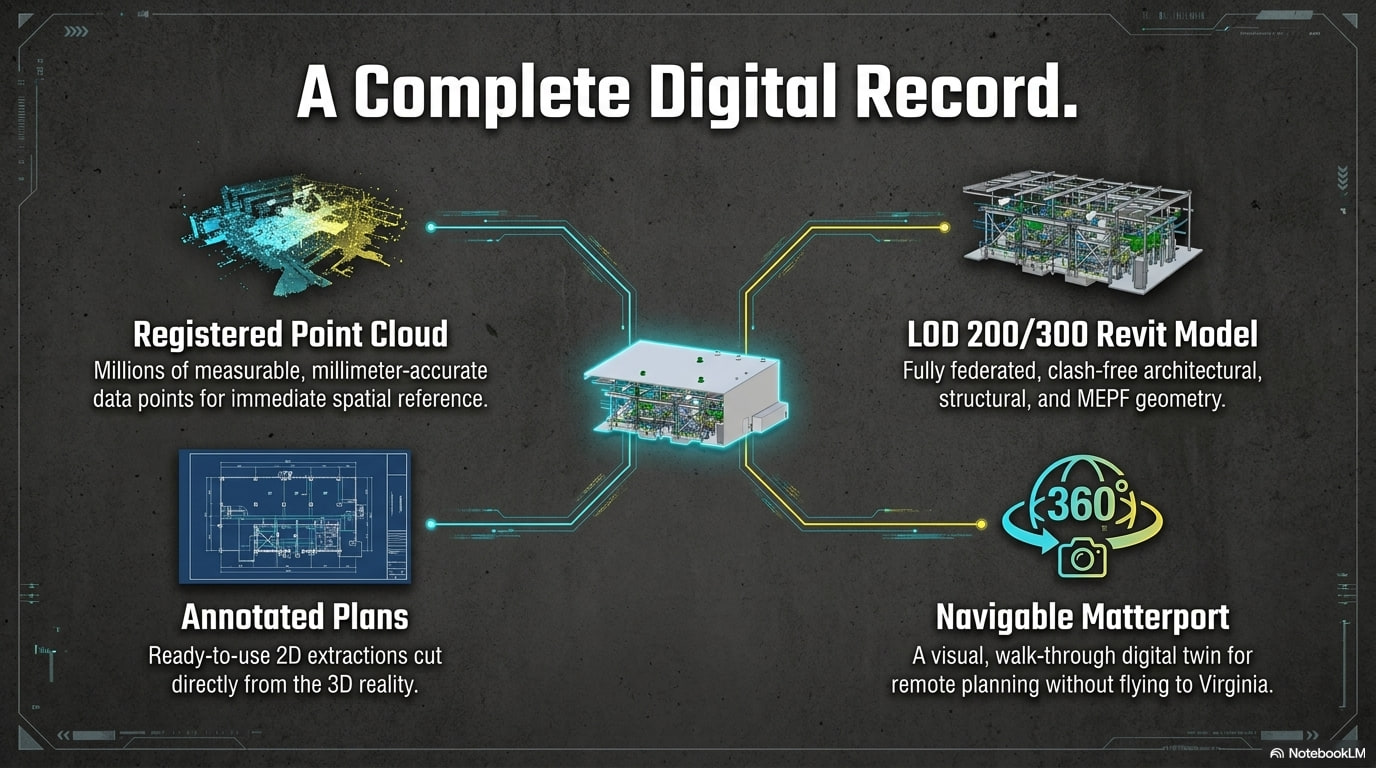
- Registered point cloud (RCS / RCP) — a complete, published point cloud of the existing conditions, the single source of truth every downstream deliverable was measured against.
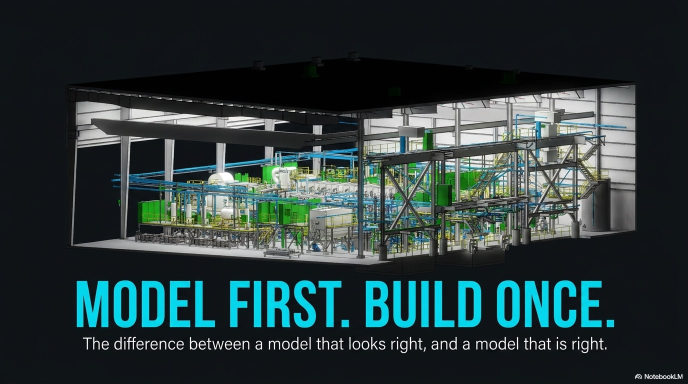
- Federated Revit model — an architectural, structural, and MEPF model of existing conditions at LOD 400 (walls, floors, roofs, columns, beams, equipment, air terminals, lighting, electrical, sprinkler, and standpipe) built to match the cloud, not the 2005 drawings.
- 2D documentation — annotated floor plans and reflected ceiling plans, plus CAD files, drawn directly from the as-captured model for planning and downstream coordination.
- Navigable Matterport — a walkable digital twin of the space the team can revisit remotely, useful long after the model is delivered.
- QC at every milestone — portions of the model were checked back against the point cloud throughout drafting, so accuracy held from capture to handoff.
Interactive 3D Model
3D Model — Coming Soon
The federated Plant 10 model will be published to an interactive web viewer here. In the meantime, the registered point cloud and Matterport digital twin give the team a navigable record of existing conditions.
Powered by Autodesk Fusion 360
Tools Used
- Leica RTC360 / BLK360 laser scanner
- Leica Cyclone REGISTER 360 PLUS
- Autodesk Revit
- Matterport
- Navisworks Manage
Results
James Hardie now holds an accurate digital record of Plant 10 as it actually stands — a model and point cloud that reconcile two decades of field change against the original design. Planning, maintenance, and future capital work can start from reality instead of from 2005 drawings and guesswork.
~60% — Typical reduction in in-field RFIs when an accurate model leads the work — a typical outcome across Heleos engagements, not a measured result specific to this project.
2005 → Now
Drawings of record reconciled to current field conditions.
LOD 400
Architectural, structural & MEPF existing-conditions model.
Single Source of Truth
One registered point cloud behind every deliverable.
Service & Location Summary
This Pulaski, Virginia project shows how Heleos VDC delivers scan-to-BIM and as-built documentation for live industrial plants — capturing congested, multi-level MEP and twenty years of undocumented change so a working facility can plan capital work from reality. MODEL FIRST. BUILD ONCE.
Frequently Asked Questions
How do you laser-scan a manufacturing plant that never shuts down?
We capture existing conditions around active production — scanning between and around process equipment, conveyors, and crews with Leica RTC360 / BLK360 LiDAR and Matterport — so the plant keeps running while we build a complete point cloud of the space as it actually stands.
Why model from a point cloud instead of the existing 2005 drawings?
The drawings of record predate twenty years of field changes — rerouted MEP, added mezzanines, reinforced steel, swapped equipment — none of it documented. Modeling from the registered point cloud captures what is really there, so the team builds against reality rather than outdated design intent.
What does an LOD 400 existing-conditions model include?
An architectural, structural, and MEPF Revit model — walls, floors, roofs, columns, beams, equipment, air terminals, lighting, electrical, sprinkler, and standpipe — built to match the registered point cloud and quality-checked against it at every milestone.
What did Heleos VDC deliver on James Hardie Plant 10?
A registered point cloud (RCS/RCP), a federated architectural/structural/MEPF Revit model at LOD 400, annotated 2D floor plans and reflected ceiling plans with CAD files, and a navigable Matterport digital twin of the plant.
Project Location
James Hardie's Plant 10 in Pulaski, Virginia is one of the largest fiber cement manufacturing plants in the world — roughly 40,000 square feet of production and warehouse space that has run continuously since 2006.
James Hardie Plant 10 — Pulaski, VA
Coordinates: 37.0515, -80.7787